
In the world of electronics manufacturing, reliability is not just a feature—it’s the foundation. From complex industrial controllers to the everyday devices in our homes, the performance of a product hinges on the integrity of its Printed Circuit Board (PCB). But how can you guarantee that every single component on a board is correctly placed, connected, and valued before it ships? This is the central question that leads us to a critical manufacturing process. So, what is in circuit testing? In-circuit testing (ICT) is a vital aspect of this process.
Table of Contents
In simple terms, in-circuit testing is an automated test that verifies the electrical connections and the individual components of a populated PCB. It’s a powerful quality control method that checks for manufacturing defects immediately after assembly, ensuring each board meets its exact design specifications. This guide provides a complete overview of ICT, its procedures, and its indispensable role in modern electronics production.
The Core Principles of In-Circuit Testing (ICT)
? A Complete Guide for Professionals")
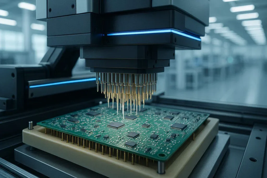
At its heart, ICT works by checking the integrity of a PCB “in-circuit”—meaning while all the components are already soldered onto the board. To understand what you mean by in-circuit testing in a practical sense, you need to know about its primary tool: the “bed of nails” fixture.
This is a custom-built test fixture containing a grid of spring-loaded pins (pogopins) designed to make electrical contact with specific points, or “test pads,” on the underside of the PCB. When the board is pressed onto this fixture, the tester can:
- Isolate and test individual components: By applying specific voltages and measuring the response (current, resistance, capacitance), the ICT machine can verify that resistors, capacitors, diodes, and other components are the correct type and value.
- Check for continuity: It confirms that there are no “opens” or breaks in the circuit traces where connections should exist.
- Identify shorts: It ensures that there are no unintended electrical connections between different parts of the circuit.
The ICT machine compares these real-world measurements against the expected values derived from the original PCB design files, instantly flagging any discrepancies.
Why is In-Circuit Testing Crucial for PCB Manufacturing?
While there are many types of tests, ICT remains a cornerstone of high-volume production for several key reasons. It provides a level of assurance that is difficult to achieve otherwise, directly impacting quality, cost, and speed.
Ensuring Quality and Reliability at Scale
When producing thousands or millions of boards, manual inspection is impossible. ICT automates the verification process, testing 100% of boards on the line with unparalleled consistency. This guarantees that a manufacturing defect on one board is caught just as reliably as on the ten-thousandth, building a foundation of product reliability.
Early Fault Detection and Cost Savings
The golden rule of manufacturing is that the earlier you catch a fault, the cheaper it is to fix. A misplaced resistor found during ICT might cost pennies to correct. The same fault discovered after the product is fully assembled and in the field could lead to costly recalls, warranty claims, and significant damage to a brand’s reputation. ICT acts as a critical quality gate, preventing defective boards from moving down the production line.
? A Complete Guide for Professionals")
Speed and Efficiency in Mass Production
An ICT cycle for a typical board takes less than a minute. This high speed allows testing to keep pace with rapid assembly lines, preventing bottlenecks. The detailed fault reports also allow technicians to quickly pinpoint the exact location and nature of a problem, drastically reducing repair and rework time.
The In-Circuit Testing PCB Procedure Explained
Implementing an effective in-circuit testing PCB strategy involves a structured process that moves from design to execution. Understanding this PCB testing procedure is key to leveraging its full potential.
Step 1: Fixture Development (The “Bed of Nails”)
The process begins with the design and fabrication of the custom “bed of nails” fixture. This requires careful planning to ensure that test pads are accessible on the PCB layout. The fixture is a significant upfront investment, but it is essential for the high-speed, automated nature of ICT.
Step 2: Test Program Generation
Simultaneously, engineers develop the test program. Using the board’s CAD data and bill of materials (BOM), they create a software script that tells the ICT machine which points to probe, what signals to apply, and what measurements to expect.
Step 3: The Testing Process
Once the fixture and program are ready, the production testing begins. An operator places a PCB onto the fixture, and the machine takes over. The fixture engages, the test program runs, and within seconds, the board receives a “pass” or “fail” result.
Step 4: Fault Reporting and Analysis
If a board fails, the ICT system provides a detailed report. It will typically identify the specific component or net that failed, the type of fault (e.g., “Resistor R22 is open,” “Short between Net 5 and Net 7”), and its physical location on the board. This allows for rapid diagnosis and repair.
When to Choose ICT Over Other Testing Methods
ICT is a powerful tool, but it’s one part of a larger quality assurance ecosystem. It excels in high-volume, mature production environments where the product design is stable. For low-volume runs or prototypes, the high cost of a custom fixture may not be justifiable, making methods like Flying Probe Testing (FPT) a better alternative.
Furthermore, ICT verifies assembly and component correctness, but it doesn’t typically test the board’s real-world functionality. For that, Functional Circuit Testing (FCT) is required. The most robust manufacturing plans often use a combination of methods. Understanding how to balance these options is crucial, and a manufacturer with a comprehensive PCB testing knowledge base can help you develop the perfect plan. To learn more about how ICT fits into a broader quality plan, you can explore different PCB testing methods and see how a multi-layered approach ensures maximum reliability.
Partnering with an Expert for Your Testing Needs
Successfully implementing an ICT strategy requires deep expertise and a focus on long-term value. The right partner doesn’t just run tests; they help you design for testability from the very beginning and analyze results to continuously improve manufacturing outcomes. They understand that robust testing is not a cost center but an investment in quality and brand reputation.
A good partner works with clients to:
- Analyze their production needs.
- Calculate the ROI of robust testing strategies.
- Make informed decisions that protect their bottom line.
- Ensure the product is built correctly and reliably, every single time.
The Final Word on ICT
So, what is in circuit testing? It is more than just a step in a PCB testing procedure; it is a strategic process for ensuring quality at scale. By catching manufacturing defects early and efficiently, ICT protects your investment, your customers, and your reputation. In an industry where precision is everything, in-circuit testing provides the confidence that what you designed is exactly what you built.